Thursday, May 29, 2008

Alberta Highspeed


Getting high speed internet was was an easy task once we had electricity. We went with a company called Alberta Highspeed for two reasons. First, one of the towers that they broadcast from was in direct line of sight from our west window and practically across the street! (picture on the bottom) and Second, we knew the owner of the company. The picture to the top shows the antenna that Alberta Highspeed installed outside our west window. There is a cable that goes from the antenna into the house. That cable was plugged into our router and BINGO! We had access to the internet! Both my husband and I were concerned about getting high speed internet once we moved to our farm, but this was easy, thanks to Alberta Highspeed.

The benefites of having electricity


Shortly after we got electricity, my husband was able to get the cold running water running. We had all the pipes in place and he was getting all the other necessary parts together, but we could not get it running until we had electricity! This picture shows some of our plumbing setup. The big silver thing on the left is a big storage tank. We pump water from our well into the storage tank and then pressurize the house from there. This removes strain from the well pipes.

After we got the water running, we could get the flush toilet working. That was a real step up from the outhouse!

Raising the tower


The raising of the tower for the final time with the wind turbine on it was exciting. The neighbors came to watch and help. Safety is a prime concern - our rule: all winching must be done from outside the crash zone . The tower weighs 1500 lbs and the turbine adds just 200 to this. The manual recommends using climbing ropes of specific strengths and cautions about knots. It also uses vehicles such as light trucks. We chose to use 5/16" galvanized wire cable as it is far stronger and easier to get. Some very important safety considerations are: use only thimbles, clips and blocks that are intended for the purpose, never use a block without a gate or latch and never loop the wire over something such as ball hitch. Murphy says: If it can come undone it will!
We used a combination of tractors and winches. Winches give the slow steady pull needed at the beginning of erection and the end. A tractor in first gear will creep at 1 mph - no truck can do that. Our winches were mounted on the draw bar of the tractor. If you use a stationary truck you will need to mount it on the hitch preferable class 2 or higher.
Near the end of the erection a tipping point is reached where the tower and gin pole are just balanced. At this point the gin pole is still some 8 feet in the air!. As you go past that point the gin pole will come down fast. The manual says to catch it and lower gently - IT WEIGHS 500 Lbs.! Unfortunately we could not find an expendable village idiot. Our solution is quite simple - we ran an extra 1/4" wire cable from the lower guy wire point through a block on the piling opposite the gin pole to another winch. This cable allowed us to lower the gin pole slowly and also allows us to pull the tower down for service. When pulling the tower down, the alternative is to swing on the guy wires like a deranged monkey! - -sorry I did not get a picture of my 250 lb buddy trying it! When pulling the tower down, the same tipping point is reached were we transfer the load from the pull down winch to the erection winch. It is absolutely essential that the erection cable be controlled and snug. We added a permanent safety cable from the end of the gin pole to the piling so the gin pole can not go past 100 degrees.
Once the tower is up and the gin pole down the gin pole has to be secured to the piling with a 3/4" bolt and nylock nut as detailed in the manual that comes with the kit.

Finally, after all the preparation, the tower was raised and we had electricity! I was so excited.

Attaching the blades and tail piece

The wind turbine was inserted in the end of the tower and bolted on. The tail piece was attached and the blades were attached to the wind turbine. The details are covered in the installation manual from Southwest Wind Power.

Building a stand and the electrical doghouse


Since the blades of the wind turbine were each nine feet long, they needed to build a support stand before they could attach the wind turbine to the tower and attach the blades to the wind turbine. The stand is shown in this picture with the wind turbine and blades attached to the end of the tower. They also had to build a doghouse for the electrical connection and the turbine break. The inside of the doghouse is shown above.

Preparations for raising the tower


Once the piling caps were set, the tower pipe was ready, and the lightening protection was in place, we needed a calm day to raise the tower. A friend of ours showed up on Labor Day weekend and his intention was to help my husband raise the tower. Since neither of them had done this before, they wanted to practice raising and lowering the tower several times before they put the wind generator on the tower. There were a few more tasks that needed to be done before they started. One was to cut the cable for the guy wires. The other was to bolt the base angles to the tower base. Once the base angles were in place, the tower pipe and the gin pole were connected to the tower base. Next, the guy wires were installed and connected to the side anchors. To raise the gin pole they put a block on the front end loader, used some of the guy wires and followed the directions in the manual that came with the tower kit. After the gin pole was raised, they attached the guy wires from the gin pole to the tower, which was on the ground, and pulled the gin pole down which raised the tower. They practiced this several times. One time, before raising the tower, they set it up to drop a weight with a string attached to it down the tower as it raised. The string was later used to to pull the electrical wire through the tower. At first they used the tractors to raise and lower the tower, but that was later replaced with winches, which was much safer.

Wind Generator

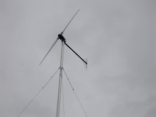
We purchased a Whisper 500 battery charging wind generator and a seventy foot tower kit from Sunfind Solar Products. Both of these are made by Southwest Windpower. This is a three kilowatt generator.

Wednesday, May 28, 2008

Why Off Grid?

Our 80 acres is located in a valley about one mile from the Red Deer river. It seems like the wind is always blowing here, why not use it to our advantage? We decided to combine the wind with solar and that is really a great combination. Besides, our house is quite far off of the road and to get electricity to the house would have been quite expensive. We did not get a formal quote from the electric company because we would have had to pay for it, but we estimated it would have cost between $15,000-$25,000 to get electricity to the house. We decided to put that money into the equipment we bought and now we do not have monthly electric or gas bills!

Sunday, May 25, 2008

Lightning protection

Lightning can take many paths from the clouds to ground and also from the top of the tower to ground. There are four upper guy wires, four lower guy wires and the tower itself. Each one has slightly different electrical properties. Protection from lightning requires reducing the differences. To do this we need to 'bond' all five bottom connections together. In our system there are copper wires that go undergroundfrom each of the guy wire bottoms to a central point next to the tower, this is also connected to the tower. We drove a 10 ft grounding rod down next to the central piling. All ground wires from the guys and the tower connect to this and also to a piece of rebar that extends from the rebar cage in the piling. Thus we ground through the rod and the piling. Concrete is not an electrical insulator!

To date we have no record of strikes. We have many tall communication towers in the vicinity and a hill to the east that is taller than our tower so this may not be surprising.

On last point the Outback equipment comes with lightning arrestors built in.

Digging a trench

Before we could install the wind turbine, my husband had to dig a trench from the wind generator tower to the house for the electric cable. Again, he used his CAD digger. The tower is 250 feet from the house. The trench was three feet deep. After the trench was dug, he and our friend Paul pulled three strands of RW 90 #3 AWG copper wire through 1.25 inch conduit. Three strands were needed because the wind powered generator is three phase. One end of the wire went into the house and was connected to the wind controller. The other end would go up the tower to the wind generator. After the wire was pulled through the conduit, the trench was backfilled.

Another view of the batteries


This is a side view of the battery racks. There are a total of 32 Surrette 460 Ahr deep cycle 6v batteries, which store enough electricity to power the house for three days if there weren't any wind or sun. If needed, the batteries can also be charged using a gas powered generator, but last winter (2007-8) we only had to run the generator about 12 hours. December and January are the months when we produce the least amount of energy. The 48 volt battery bank feeds the Outback inverter which produces 115V AC. This is routed through an autotransformer, also supplied by Outback to produce 240 Volts AC. A standard service panel is used to provide standard house wiring.

Mounting the powerboard


Our friend, who is a master electrician, helped my husband mount the powerboard pictured here. This was designed and put together by Sunfind Solar Products. It consists of: (from right to left) a Whisper Wind controller (from Southwest Wind), a solar controller (from Outback), a DC panel (from Outback), an inverter (from Outback), and an AC panel (from Outback). The controllers take the electricity produced by the wind and solar, respectively, and fill the batteries. The DC panel takes the electricity from the batteries and and feeds the inverter. The inverter converts 48 VDC to 120 VAC. A standard service panel is used to provide electricity to the house. The AC panel contains a transformer which converts 120VAC to 240 VAC, which we need to run our well pumps.


After the power center was mounted and wired, the battery racks were put in place. Next, the batteries were placed on the rack and connected (Safety note - remove any metal jewelry and insulate tools with electrical tape when working with the batteries).

The wind controller takes the power produced by the wind turbine and fills the batteries. it also monitors the state of the batteries. There is a light that indicates when the wind generator is charging the batteries and a display to indicate the voltage of the batteries.
The solar controller takes the power produced by the solar panels ( added in December 2006) and fills the batteries. It also monitors the state of the batteries. It has a display which indicates how many watts the solar panels are currently producing. Iit also indicates the voltage of the batteries.

Connecting the pipes


Our seventy foot tower is made up of three pipes connected together. The sections were carefully marked and drilled according to directions. A piece of aluminum flashing wrapped around the pipe was used to draw a line around the pipe and to mark the locations of holes around the pipe.

The tower kit we purchased included connectors which were 18 inch lengths of slit five inch pipe. The connector needed to be collapsed so it could be inserted into the pipes. My husband used a pair of vice grip chain wrenches, shown in the pictures, to collapse the connector. The connector was then inserted in the first pipe. The second pipe was greased on the inside and slid over the other half of the connector. The chain wrenches were released. A block of wood and a sledge hammer were used to finish driving the pipes together. They were then drilled and bolted together. The 35ft gin pole was constructed the same way.
The assembly was performed at the erection site with the pieces being moved around with slings and a front end loader. The tower weighs about 1500 lbs. The guy wires were measured and cut (with a zip cut blade on an angle grinder) to prescribed lengths and attached to the tower and eyebolts in the pilings. The Southwest Wind manual is easy to follow and exact.

Wind generator tower preparations

For the wind generator tower, we purchased four pieces totaling 105 feet of schedule 40 five inch pipe. We also purchased a Whisper 500 70 foot wind generator tower kit from Sunfind Solar Products which was made by Southwest wind power. After one cut, we ended up with five lengths of pipe. Two for the 35 foot gin pole and three that would make up the seventy foot tower. My husband marked and drilled the pipes for the guy wires, wind turbine, bottom bolts and connectors. Then he cleaned, primed and painted the the base angles and the pipes which are shown in the pictures here.

Saturday, May 24, 2008

Battery rack


Early in the summer of 2006, Caleb Schmidt from Sunfind Solar Products delivered the 32 batteries we ordered for our power system. My husband did not want the batteries sitting on the concrete floor and he wanted to stack them so they would not take up so much space, so he designed and built two battery racks which he had powder coated. The pictures above show the racks with the without the shelfs. Each rack would hold sixteen batteries, eight on each shelf.

Wind tower pilings and piling caps


When the crew had the pilings dug for the house, we also had them dig and pour five pilings for the wind generator tower. However, we did not have the hardware for the top of the pilings at that time, so they did not pour the top three feet. The plan was to pour the piling caps when they built the dome.
Unfortunately, when they came back to build the dome, there was a concrete shortage and the weather had turned cold, too cold to pour concrete outside without heating it, so they left it for us to do in the spring. This turned out to be a bigger task than expected. Gophers has piled quite a bit of dirt on the existing pilings, so a quite a bit of preparation was needed before we could have the piling caps poured. We finally had them poured at the beginning of July. The picture on the bottom is one of the four pilings that would secure the guy wires. The picture on the top is the center piling that would secure the 70 foot tower.

When we were first planning the installation of the tower we read through the manual and realized that the pilings recommended were not sufficiently deep to go below our 6 ft frost line. Most water pipes here are 8 ft deep. The engineer for the house agreed they were not adequate and recommended we use the 18" diameter 25ft deep pilings that were used in the house. We recommend that local engineers be consulted for all installations.

The Septic tank


Once the weather turned nice, we had to start concentrating on outdoor projects that needed to be done before winter came, so we put our indoor projects on hold, except for rainy days. Our first project was to find where the rough plumbing came out from under the ring beam and to dig a hole for the septic tank. My husband used the CAD digger to dig the channels and the hole. Once dug, they delivered the septic tank in mid July and placed it in the hole.

Wiring and plumbing

Once the major framing was done, we started to run the wires for electricity and the pex pipe for the plumbing. It would be a while before we got water and electricity, but it was another step toward completion.

Our summer home


At the end of November, 2005, we signed a contract to sell our home in town to someone who came to see the dome being constructed. At that time, my husband thought we would be ready to move into the dome around June 1, 2006. Well, when that time came, we were no where NEAR ready to move in, so we moved all our boxes and furniture into the dome and we moved into our 13 foot 1960's vintage camper, seen in this picture. We lived in the camper for June, July, and August while we continued to work on the dome. Thankfully, it was a beautiful summer.

Framing for the second floor loft


When you first enter the dome, this is what you see. In the center of the dome is a utility area and there is a second floor loft above the utility area. It was originally going to be just for storage, but as we were putting the floor down, I realized that this was going to be a really unique area, so we are going to finish it for use as an area for our projects.

Friday, May 23, 2008

Front and west windows from the outside


The upper picture shows the two bedroom windows which face north and mortheast and the front door. The lower picture shows the front door and west window from the outside.

Inside view of Front Door


This picture is a view of the front door and west window from the inside.


The window below the west window is a damaged bedroom window.

Wednesday, May 21, 2008

A view from the inside


We were so excited to have windows! This is a picture of the three south windows from inside the dome.

South windows installed!


In May, my husband and I installed the two bedroom windows. Our friend helped install the west window, and we had a crew install the three south windows and the front door because they were massive windows and we did not want to risk anything going wrong. The crew got the windows in place and stood up. My husband wanted to finish the installation himself. This picture shows the three big windows that face south. You can also see the chimney in this picture.

Window delivery


It took three or four deliveries before the entire window order was complete. In this picture, the west window has been installed and the three big south windows and the front door are waiting installation.

Removing the plywood from the bucks


In this picture, my husband is cutting away the remaining plywood from the bucks in preparation for the windows to be installed.

Window preparations


Winter was over and spring was approaching. The majority of the framing was done, so we ordered the widows! In this picture, we were preparing for the window installations

Working on the Chimney


This is a picture of my husband and a friend working on the chimney.
Before the concrete was sprayed on the inside of the dome, we had to know where we needed openings for things to go through, such as the chimney, wires, etc. Void forms were created and inserted prior to the concrete being sprayed.In this picture, they are removing the void form before the chimney was inserted in the opening.

Friday, May 9, 2008

Kitchen walls


This series of walls divide the kitchen from the utility area. The kitchen will be on the right of the walls, the utility area on the left.

Bedroom wall

I think this is the wall between the two bedrooms. This wall went up in one piece and was a challenge to construct correctly and a challenge to stand it up.

East bathroom

Remember those first two walls? Well, this picture shows the wall that completed the bathroom.

Thursday, May 8, 2008

West bathroom


This picture shows the framing for the west bath. There is storage above the bath and the master bedroom with a large walk in closet is on the right.

How to curve a two by four


To the left is a closeup of the first curved wall. The curved two by four was made up of two one by fours that have been slotted so we could bend them. The picture above is of the jig we used to create the curved beams. The slotted one by fours were glued together and sometimes also screwed together. The curved walls were anchored to the dome wall and to the floor with concrete anchors.

Framing the walls

On March 13, 2006 we started framing the walls. These are the first two walls we did. There will be a bathroom between the walls! The wall on the right was only a partial wall at the time this picture was taken, it got extended. The curved surface and the unevenness of concrete was a challenge we had to deal with.

Painting the inside

After the floor was poured, we decided to paint the inside of the dome since we had removed everything from the inside to pour the floor. We rented an airless paint sprayer and painted the inside sky blue. It really brightened up the inside because the concrete itself was rather dark.

Floor Vents


The picture on the left is a picture of the floor vent after we removed the void form. Next to it is the 4"x14" floor grate that is inserted in the vent. The picture on the top is a picture of the floor grate inserted into the vent